- - Un-amplify Pressure Sensors(2)
- - Ceramic Pressure Sensors(1)
- - Amplify Pressure Sensors(2)
- - Altimeter Pressure Sensors(2)
- - Micro-Pressure Sensors(1)
- - Stainless Steel Pressure Sensors(1)
- - Digital Output Pressure Sensors(0)
- - PC board pressure sensors(5)
- - Intersema(40)
- - Pressure transmitters(2)
- - Weight sensors(2)
Industry News
Optical fiber current sensor
2010-12-13 12:41:50
Abstract: This paper uses two different concepts based on Optic current transducer ( OCT ). One is the traditional transformer based on the concept of OCT , the other is the concept of Faraday effect based OCT . The paper also describes the first based on OCT -made test products and its ABB product similarities and differences.
Key words: Optic fiber ; Optic fiber current Sensors ; Faraday effect
1 Introduction
Optic fiber current transducer ( OCT ) and the conventional current transformer of the difference is: the energy required to send a different current, low manufacturing cost, operation and safety performance.
Early in the 20th century, 50 years, some manufacturers have this idea: If current transformer ( TA ) operation of the power and protection are all set in the insulated platform, so that you can use low-voltage insulated TA instead of high voltage insulation of the TA . They do want to have done so. Switch the gate opening and closing insulated rotating electromagnetic signals to pass the bar.60 years later, the use of Optic fiber to convey information, and relay protection, Optic fibers and electronic equipment required for operation of high voltage power supplies are still on the platform.
70 early, ABB transformer is the company developed to probe OCT . The biggest improvement is that the actuator Sensors with Optic energy required for fiber to light energy transmitted to the Sensors . This can be all the protection and monitoring equipment are placed at ground potential and the operator place. This will maintain the original Sensors of the advantages and overcome the original Sensors shortcomings [1] .
This article introduces the ABB company products, compare the way of domestic samples [2] and the similarity of foreign products and different points. This article also describes today's new technology, which is based on Faraday effect ( Faraday effect ) principle OCT .
2 the transformer for the Sensors 's Optic fiber current Sensors
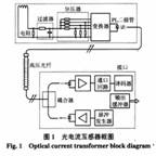
Figure 1 is the ABB company transformer is the Sensors of the OCT in the block diagram. It can be divided into three parts: the high-pressure side of the Sensors , Optic fiber loop and interface circuit.
(1) high-pressure side of the Sensors
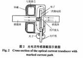
Figure 2 for the Sensors assembly and cross-section diagram. Where arrows indicate current flow. Since the Sensors for the current transformer, so the secondary can not open, you must connect a resistor. This resistance also allows the current signal into a voltage signal. Voltage signal by the filter into a voltage divider, voltage divider ratio automatically according to the partial pressure converter. After the partial pressure signal by the A / D converter into a digital signal, the digital signal by the sampled through PL diode by the Optic output. These parts of the literature [2] and the literature [1] are similar. Second, the difference between the literature there are two points: OCT power from different sources and sampling frequency are different.
1 ) OCT power from different sources. The literature [1] in the high-pressure side of the Sensors operation of the power required and the energy needed for the sampling command from the interface circuit at ground potential within the laser pulse source, is by means of Optic fiber transmission. Pressure Sensors transmit digital signals sent to the ground potential at the interface also depends on this fiber .
Within the interface circuit of light detection diode Optic signals into electrical signals, amplified by the loop from the openings to the decoding circuit, the digital signals into analog signals, then through the output buffer circuit (such as pulse width modulator ( PWM ), etc.) into a suitable circuit protection and monitoring the current required forms.
The literature [1] The Sensors is not in the high side power devices, simple and reliable components it contains. Between the high side and the ground potential to the pure insulator Optic fiber for isolation, which is very safe and reliable.
The literature [2] of the Sensors 's power supply from the other a set of current transformer, is rectified after the second current into direct current as its power supply. Can not open the secondary circuit, so when a current is 100% change to tend to zero, the proportion of the supply voltage will also change. Shows the supply voltage fluctuation is large. Microprocessor and the light-emitting diode ( LED ) is able to withstand such a large change in voltage is worrying. The
2 ) different sampling frequency. The literature [2] The sampling frequency is 5 0 Hz , or 5 0 Hz quasi-synchronous sampling, hope and the power grid frequency deviation of less than 0.5% , at the same time be compensated by software to reduce its error. The literature [1] used a sampling frequency of 80 0 Hz , synchronized with the grid simply does not care about sync.
I believe that the experience of other countries is a worthy lesson.
The literature [1] described the OCT , which uses the current probe, although the conventional transformer-type, but because the first and second insulation between the low, so the core length can be greatly reduced, and set a gap, so that hard core saturation, improved dynamic characteristics, coupled with the second resistive load is small, so the energy consumption is very small and very stable.
In Figure 1, the Sensors in, PL diode is a special application for gallium aluminum arsenide ( GaAlAs ) diode. It is the electrical signals into light signals the key components.
Electronic converter circuits using special low-voltage low-power CMOS circuits. Its operating power from the PL diode, its voltage is lower than 1.0 V, power consumption is less than 15 0 mW .Sensors of all electronic components are encapsulated in a single chip, which reduce energy consumption, improved reliability and enhanced noise immunity is very important.
( 2 ) Optic fiber loop
ABB 's OCT signals transmitted by a digital signal. The collected signal level as long as the resolution to meet the requirements, light guide fibers without excessive requirements.OCT 's accuracy depends on the Sensors itself. Standard Optic fiber and transparent inner core diameter of the outer cover, respectively 10 0 mm and 140 mm .Fiber inner core and outer cover of the refractive index change is the mutation of the ladder-shaped. The fiber to meet the requirements of the resolution of its maximum allowable length is 50 0 M .
When the Optic fiber used in high-pressure system, the laying of the insulation and mechanical strength are very important, so high fiber laying the appearance of a high-pressure synthetic materials, their mechanical strength can crawl away and meet the requirements. The Optic fiber is easy to buy in the market.
( 3 ) part of the interface circuit
Optic interface section includes a one light source and one a light module. Optic modules on the one hand can be at ground potential at the source of excitation laser light through the fiber to the pressure Sensors , on the other hand can detect the high ground at the Sensors via fiber Optic signal transmission back. Laser diodes with a wavelength of light source 780 mm . Optic module is coupled with the performance changes in the length of light waves. It is different from the refractive index of light and the composition of Optic filters.
Interface electronics, including laser-driven electronic circuit. It is the light source power is constant. There is also an interface to be able to detect the pressure Sensors to the digital transmission signal light pulse circuit, the light signal is transformed into electrical signals, amplified and then through the decoder ( D / A ) to the output buffer, and then output suitable for protection and control with the current signal (eg, by PWM and other means.) At that time the design of OCT in the sampling frequency of 80 0 Hz . Under normal operating conditions it is reliable. Low-voltage low current operation of the PL diode security is very beneficial.
3 Faraday effect based OCT
Now on the market to buy into the OCT is not a Transformer-like but most of Faraday effect based on the principle of the OCT . Faraday effect works as follows:
Straight line radiation placed in a magnetic field polarized light launched into Sensors, the magnetic field strength H in the direction parallel to the polarization of light. When the polarized light Optic Sensors acts in a distance L after the arrival of light-sensitive outlet when a deflection angle q , as shown in Figure 3 below. The size of the deflection angle of the magnetic field strength H is proportional. That![]()
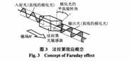
Where V is magneto-Optic crystal Velde ( Verdet ) constant, RAD / A ; L for the polarized light through the Optic Sensors acts away.
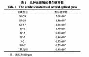
Optic Sensors is generally dense and heavy texture of flint (
According to Ampere's law![]()
Where A is a constant.
With the current detection methods can not distinguish the polarization of light deflection angle θ , but only measured by the polarization modulated light energy. Light energy is and the Optic field intensity E is proportional to the square. In other words, you need plus a deflection angle of light used to determine θ of the analyzer, this analyzer is the first 2 months of light polarizer. From the first 2 months of light polarizer (analyzer) the light deflection from the α angle, which with the first one out of a light polarization control of light deflection angle difference between the π / 4 . Is well known that each plane can be decomposed into any two mutually perpendicular planes. Therefore, deflection angle θ of the plane can also be decomposed into two planes, one a plane and the deflection α parallel to the plane, and the other one a plane and α perpendicular plane. So that the polarization of light input energy P in . After a light Sensors and light after the analyzer to detect the polarization of light energy for the P DET , the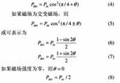
If the current transmission, and then q is a constant. Based on the Faraday effect which OCT can measure not only AC current can be measured DC current.
Figure 4 is based on Faraday effect of OCT in the flow chart. Figure 5 is based on Faraday effect of OCT structure diagram.
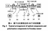

Figure 4, the light source is at ground potential, and its non-polarized light beam (a) . Beams through Optic fiber into the high pressure at the Faraday effect-based OCT section 1, a light polarizer, Optic polarizer non-polarized light into polarized light (b) . After a Faraday Optic Sensors light deflection angle after the polarization q (c) .q plane down into two planes, one in a plane parallel to a plane, another one in a plane perpendicular to a plane ((d) . After a light analyzer (the first 2 months of light polarizer) after perpendicular to a plane of the beam is eliminated (e) . After the fiber , after multiple reflections within the polarized light has become a non-polarized light (f) . Therefore, in ground potential at the light detector to detect non-polarized light. In Figure 5 can be seen, the light Sensors close to the high voltage bus, because here the magnetic field strength H max. Figure 4, the light detectors in the 2 species. Most with PN junction diode light detectors plus Optic amplifiers, there is also transistor ( photo-TRANSISTOR ) photodetector. Optic transistor and ordinary transistor different in that its base is triggered by light. So after Optic transistor can be turned into electrical signals and Optic signals have been amplified.
Optic signals into electrical signals through the Optic detector can be carried out after the operation. Eq (7) minus the type (6) divided by P in can be sin2 q .
In order to improve dynamic range, q generally use the ± 5 ° [1] . For the interface, OCT output of only a few mA , and in order to avoid noise interference, the old TA were often secondary current 5A or 1A . Order and the old electromechanical relay protection and instrumentation match, you must install the interface amplifier, which increases the complexity of the equipment, and investment and also increased the dry sound. Modern instrumentation and protection for the static type (E type), the consumption of energy is very small, so the development of new measurement techniques and protective equipment will be pressure to change the digital signal directly signal is an urgent task facing the [1] . But in no case the Optic signal from the high side to be fitted with Optic insulation measures to ensure safety.
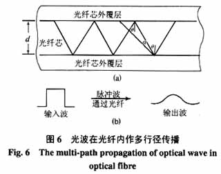
Light in the fiber within the act. Light of the incident angle is greater than q only when total internal reflection. This is the fiber of the necessary but not a fiber optic communications sufficient condition. If the literature [1] , as the light source wavelength of 78 0 nm and the fiber of the fiber core and fiber core diameter of the outer cover, respectively 100 mm and 140 mm , is clearly too thick. Greater than the total reflection angle (ie, q a ) of the light too much. Obviously, the wavelength of light under certain conditions, the travel angle of reflection of light is relevant. This means that the waves had the same starting point, but points of light waves travel is different, and therefore the time of the light to reach the terminal angular wave pulse through the fiber , it becomes a gentle wave, as shown in Figure 6 Fig. Therefore, Optic fiber must be a single trip. The literature [1] pointed out: The digital Optic , the digital level to identify requirements that the Bank can achieve its allowed maximum transmission distance of about 50 0 M .
4 Conclusion
( 1 ) all of the OCT is the Optic fiber as insulation and in light signaling current signal.
( 2 ) to probe the conventional transformer OCT , the signal transmission in digital form on Optic fiber requires more loose. The principle based on Faraday effect of OCT in the Optic signal to analog signal representation of fiber the more stringent requirements.
( 3 ) conventional transformer-type OCT , the power transformer should not be taken from the active probes.
( 4 ) Based on the principle of Faraday Effect OCT is the current hot research.