- - Un-amplify Pressure Sensors(2)
- - Ceramic Pressure Sensors(1)
- - Amplify Pressure Sensors(2)
- - Altimeter Pressure Sensors(2)
- - Micro-Pressure Sensors(1)
- - Stainless Steel Pressure Sensors(1)
- - Digital Output Pressure Sensors(0)
- - PC board pressure sensors(5)
- - Intersema(40)
- - Pressure transmitters(2)
- - Weight sensors(2)
Industry News
How to choose the correct voltage silicon pressure sensor
2010-12-13 15:40:17
MEMS sensor chip has been developed to the point of a large capacity pressure sensor. Sensor has temperature compensation, calibration and hybrid amplification, can be used in most of the low use of monitoring. Car . low-cost and high reliability is composed of sensing external conditions of the basic elements of vehicle, including the injection, gasoline vapor and exhaust equipment. Recent silicon sensors are used to monitor automobile tires, pipes and brake pressure. Scope of application of silicon sensors can also be extended to manufacturing packaging technologies to protect automotive components in harsh environmental conditions of use.
New low-voltage silicon sensor, you can 1 / 10 lb / in2 the pressure generated response, there are the use and production of the product. In a small range, the silicon pressure sensor has been able to measure the level of weak material change or exhaled pressure. The equipment uses a pressure sensor in the new technology to replace a lot of pressure on the use of mechanical equipment. But how can you be well in the use of choice? Way to judge is to test the traditional silicon sensors and the difference between sensors, market advantages, and you use the technical specifications of the silicon sensors.
What could be the correct composition of low-pressure sensor system ? In general, the typical silicon pressure sensor in the range of 0-0.15 psi FS between, and often can be to rise to 0-10,000 psi . Manufacturers of low voltage is defined as not the same, based on its sensor design and their production process. Response is less than 5 psi sensor generally asked not to die the same topology and technology. According to the discussion of this issue, that is, to less than 5 psi of pressure is defined as low-voltage range.
Differences in silicon technology
to form low pressure sensing silicon micro mechanical components manufactured by the same process to form a standard pressure range of components, but there are key differences. Standard range of components including the etching resistance of the thin membrane on the bridge (Wheatstone way). When the voltage source excitation offset the pressure of the formation of membrane resistance will change and cause the output voltage changes. Low-voltage silicon sensors work similar, but there are obvious features, including the processes of membrane structure and for the stress concentration of about 50% of the membrane area. Accurate film thickness and etching resistance can be placed on strategies to expand greatly the capacity of the sensor. In addition, the traditional semiconductor silicon sensor technology will also appear in scale batch production cost advantages.
Low-voltage silicon sensors are commonly used in the following three major markets:
HVAC. pressure sensor is a ventilation, heating and air conditioning systems are indispensable parts. In other application, they can monitor ventilation and air flow, to determine the volume of air, dirty filter detection of changes in the load caused the problem and control the system pressure. These require the use of products in the 0.015 psi of pressure can detect changes in the pressure difference.
Medicine . If there are no small size of the sensor can not detect many medical use of environmental changes and conditions. So designed to meet the following requirements: a relatively small sensor ( 1-2 mm ), can measure the body's fluid pressure. The catheter is generally equipped with devices, they can be inserted into the heart cavity, skull, or the uterus, real-time monitoring of difficult surgery, this one is absolutely a product of cheap goods. Respirometer for low-voltage products require sensor range in the 0.5 psi or less. These operations previously performed by mechanical pressure changes according to the time switch is executed.
Application requirements and sensor types
Because each application has its own characteristics, so you have to think in the selection process fully all aspects of the whole system. Be sure to identify the source of the input pressure, the desired output, and all relevant operating conditions. Installation position and direction, proximity and pressure source, wire stress, interface and pressure connections, determine the package to withstand the impact and influence the accuracy of the performance range. For example, in medicine in the use of sensing the pressure of the membrane components may be no package installed. Affected by temperature fluctuations in the measurement process, and must have more advanced sensors for compensation and offset calibration, so that it can eliminate the temperature coefficient of material generated. Such as humidity and pollution, the environment, will also affect the use of medical protection. Precision trade-off resulted in the adoption of certain features microprocessor control and eliminate unwanted results. System components (such as amplifiers, power supply, the control circuit A / D converter) and the compatibility of the sensor analog output signals have to hope that all the design and solution accuracy.
Each pressure sensor has the material properties, the pressure changes according to the formation of measurable output data. When you think of the technical data common detector, be sure to keep in mind their technology needs.
Silicon micro-machined materials . These products are injected into resistance from the silicon diaphragm micromechanical components, this divide can be generated in the piezoelectric under pressure changes. Including the use of physical pressure testing, medical ventilation equipment, vacuum cleaner, auto air and steam pressure.
Electronic materials . These products include variable capacitance sensor and the stress of dollars. Using foil strain gauges, deflection of thick / thin film, or adhesive foil coupling effect. Variable capacitor element binding changes in capacitance and converts it to a measurable signal. Mechanical stress and strain gauges for use in contact.
Vacuum gauge . vacuum sensor wire will heat balance of the bridge as a leg, by measuring the resistance change to detect pressure. They are mainly used to detect the vacuum chamber to the vacuum value, such as electron microscopy, and other process equipment.
This type of sensor is a piezoelectric material by the crystal, ceramics, polymers and films made of, when they are applied when the machine will produce electric polarization. These products are suitable for dynamic pressure source is not suitable for the continuous atmospheric pressure as a static situation. They can work well under harsh environment.
Variable Reluctance material . Variable Reluctance Sensor deflection in the two metal film sensor with a sensing membrane between the half-bridge configuration. Induction / impedance change results can produce a change in the AC signal. Including the use of typical low-pressure HVAC .
Understand the use of standardized
Once you have determined the design requirements, priorities can be decided on the most important selection criteria and determine which technology best suits your use. How do you determine which standards are most important? Specifications typically require certain aspects of the system parameters have to make sure. Pressure operating range is mainly, the highest priority to its general orientation. As for the volume of low pressure for the micro-mechanical equipment, you may think the premise in the price of a wider response range. With the confirmation of sensitivity and pressure range, usually arranged by grade standard order for the cost, accuracy, physical size, reliability, long-term stability, temperature performance and media compatibility.
Actual proof of performance and accuracy of temperature are often the most complex processing factors. Each manufacturer's accuracy specifications are described in their correctness, but these parameters have to be converted to comparable units to increase their comparability. To help you understand the performance specifications, the following lists the most common definition of accuracy of interpretation and the content of each of the most noteworthy changes. The first set of assumptions in the reference temperature 35 ° C .
Zero / offset . in the textbook value of the output voltage excitation is usually considered to be in the 35 ° C conditions of zero applied voltage. Generally expressed as 0 ± mV . Because the reasons for the relative change in the higher current or voltage applied will produce more offsets.
Lag of zero pressure . When the pressure sensor for multiple full-scale cycle of measurement, there will be zero repeated measurements. The units with a percentage of full scale output. The lag in calculating the performance of zero pressure, do not use the same sensor manufacturers are not the same full-scale range and the pressure is not the same number of cycles.
Pressure range of the lag . When the sensors for several pressure cycles, the output range of duplicate measurements. This value is usually the worst case was expressed as a percentage of full scale output.
Performance of the temperature hysteresis range . When the sensor used in the same temperature cycle, the identification of the range of repeatability. In other words, the sensor is subject to the maximum and minimum temperature constraints. After the reading range of recycling is the difference between the temperature range of hysteresis performance. This parameter is expressed as a percentage of full scale output. Therefore, the full scale pressure reading to determine the various temperature cycles used in the range of the worst changes.
Sensitivity . pressure variations and the change in the ratio of the output signal. Practice depends on the unit manufacturers, but the value is generally used mV / V or I / psi said. Is to determine the sensitivity of system solutions for key performance indicators.
Long-term stability . in a certain period of time, changes of scale and zero performance measure. General use mV said.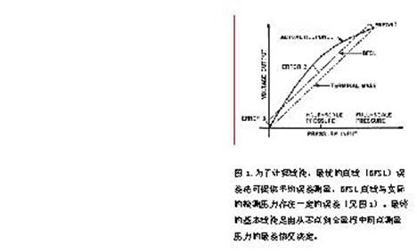 Figure 1. To calculate the linear and the best straight line ( BFSL ) error method can provide the average error measure, BFSL line with the actual pressure of certain error detection (see Figure 1 ). By the end of the basic linear scale from zero to full pressure on the middle of the worst-case point measurement decisions.
The nonlinear range . When the pressure increases, the silicon micro-machined sensor generates a proportion of output is generally low. So for the high pressure transducer is displayed in terms of lower output, linearity can only speculate about the actual instructions. There are two basic methods of linear calculations. The best straight line ( BFSL ) error method can provide the average error measure, BFSL line with the actual pressure of certain error detection (see Figure 1 ). By the end of the basic linear scale from zero to full pressure on the middle of the worst-case point measurement decisions. Generally nonlinear terminal 2 x BFSL nonlinear.
The second type of specification describes the accuracy of the temperature-related situation. When the temperature changes, all the sensors are present non-repetitive zero drift. Typical changes in bridge resistance at room temperature for about +3000 ppm / ° C ( sometimes with a mV / V / ° C that ) . However, in the case of below room temperature (typically -20 ° C ), there will be zero impedance of the slope and conversion. Under these conditions, assuming that resistance changes linearly with the relationship between temperature are invalid, so the correction factor term was incorporated into the sensor module. Good case can do to minimize the error only, the actual time used for individual manufacturers use the same standards on tolerance. Manufacturers in order to optimize its performance standards, it is not the same for each manufacturer will raise the performance indicators.
Zero temperature coefficient ( 3 ways) . This value is difficult to define exactly, precisely to require manufacturers to change. Some manufacturers use a simple linear, both in the reference temperature ( 35 ° C ) a straight line connecting the two end points, in particular the provisions of the error should be less than the ideal range of small butterfly. The second zero temperature coefficient is defined in the specified temperature range, the temperature error should be higher than the given percentage of full scale low. This is the basic measure of performance, but not widely used. No. 3 ways is to use 3 data points calculated BFSL .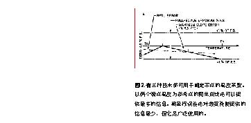
Figure 2. there are three kinds of techniques can be used to determine the temperature coefficient of zero. Endpoint temperature of two simple and straight-line reference points can provide the most information. Full-scale error method for at least the information provided equipment performance, but it is widely used.
3 kinds of technology, the first to provide the most up to data information, and section 3 species ( BFSL error) available to users with limited accuracy. The second way to provide a minimum of equipment performance information. Figure 2 shows three ways of comparison.
The temperature of zero lag . When one or more temperature sensors are used to cycle, the zero reading reflects the repeatability of measurements. After a certain cycle, zero temperature reading differences reflect the lag, generally defined as the percentage of full scale output. Therefore, the full scale pressure reading to determine the whole temperature cycle in the worst case of temperature shift.
Temperature compensation is a way to eliminate the temperature change, the use of complex mathematical models to determine the correction value thick film resistors. Run on a variety of changes in temperature requires both the operating system of compensation through the electronic system, the sensor manufacturers need to advance adjustment.
The combination of a variety of error components can be used to describe the sensor error on system performance. The following two definitions are widely used to describe the sensor accuracy:
the worst error of all relevant circumstances the sum of the single error here:
the error ( worst case ) = E1 + E2 + E3... En
The most likely error is defined as the square root of a single sum of squared errors, where:
Error ( most likely case ) = (E12 + E22 + E32 +... En2)
RMS error from the direction of.
Product Selection Table
Now you can choose, you have identified a good selection criteria, you have a list of design constraints, you can use them to make a decision. The following simple tool comparison table can help you make the decision. In general, many processes can be made in this way, of course, you compare the situation was combined with the manufacturers. Analogy, if you are designing a medical respiratory equipment, the pressure switch point may have an action of electronic circuits. Electronic switch to complete the task, but the key design parameters are size, pressure range, long-term stability and cost (see Table 1 ).
Table 1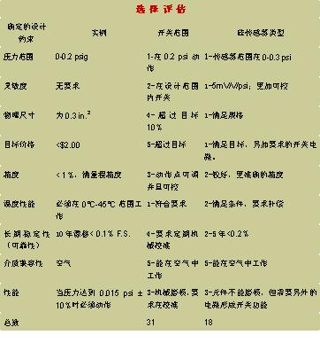
According to Table 1 provides comparison of the proposed recommendations, low-pressure sensors and switching characteristics can be compared, each product has its own advantages and disadvantages. Important is the introduction of micro-machined silicon pressure sensors can not exist prior to this selection process. In assessing the new design, you can use mechanical or silicon conditions.